In order to move our Raspberry Pi powered rover, we will need at least two DC motors to power a left and right set of wheels. The motors will be used to move the rover forward and reverse, as well as rotate left and right.
To accomplish this, we figured out how to modify the DC motor tutorial on adafruit.com to go from controlling one DC motor to two independent DC motors. Controlling two DC motors was accomplished with one L293D dual H-bridge motor driver chip, additional wiring configuration and code modifications.
Let's first look at the L293D dual H-bridge motor driver and GPIO wiring:

In the above figure, all connections in blue and purple are used identically in the original tutorial which demonstrates how to control one DC motor.
Used to control direction of motor 1:
- GPIO 4
- GPIO 17
Pulse with modulation control (PWM):
- GPIO 18
DC motor connections:
- M1+
- M1-
Power source connections:
- Battery+
- 5v Pi
Ground:
- GND
The annotations in green are what was added in order to get the second DC motor to work with the shared L293D dual H-bridge motor driver.
Used to control direction of motor 1:
- GPIO 23
- GPIO 24
Pulse with modulation control (PWM):
(NOTE THIS IS INTENTIONALLY SHARED WITH MOTOR 1!)
- GPIO 18
DC motor connections:
- M2+
- M2-
Ground (not sure if necessary):
- GND
At this time, we are using the PWM kernel module included in Occidentalis v0.2. This module is used to controll the rotational speed of the motors, which should both rotate at the same speed. Having both motors sharing GPIO 18 seems to work fine. The drawback of using the PWM module is that there is only one, and we cannot use it for both DC motors and servos. If we find that the default maximum speed of the two motors is fine, we may later free up GPIO 18 in order to add a servo.
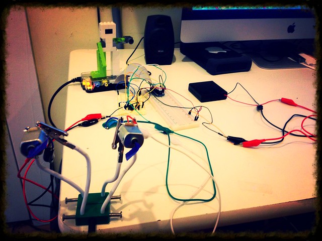
Our large breadboard was getting messy from other projects, and this one requires a good amount of wiring, so I cleaned out everything from previous projects before starting this one.
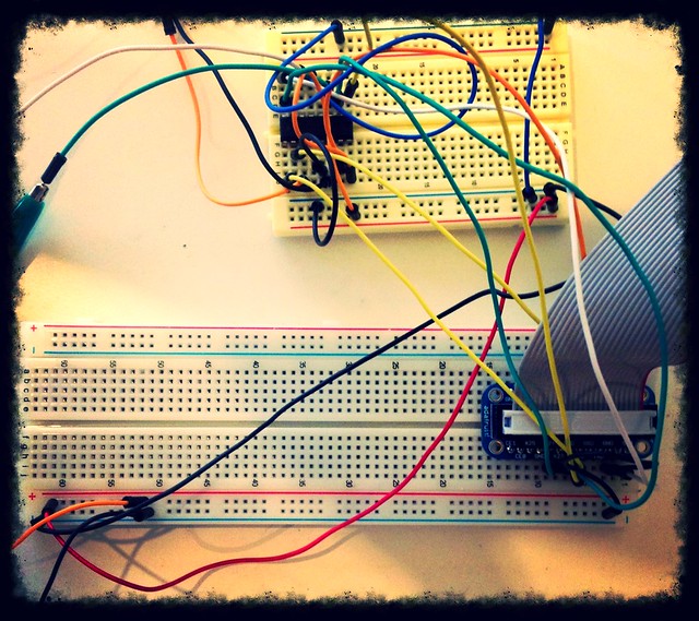
I place the L293D dual H-bridge motor driver on a separate half-size bread board in order to keep all motor related wiring isolated on one board and left the GPIO breakout on the large breadboard (since we will be connecting more stuff to it later on).
Lets now look at the code. In order to have efficient code for the motors, I created a Motor class, so we can instantiate two motors with one class definition.
Motor class:
- class Motor(object):
- def __init__(self, in1_pin, in2_pin):
- self.in1_pin = in1_pin
- self.in2_pin = in2_pin
- GPIO.setup(self.in1_pin, GPIO.OUT)
- GPIO.setup(self.in2_pin, GPIO.OUT)
- def clockwise(self):
- GPIO.output(self.in1_pin, True)
- GPIO.output(self.in2_pin, False)
- def counter_clockwise(self):
- GPIO.output(self.in1_pin, False)
- GPIO.output(self.in2_pin, True)
- def stop(self):
- GPIO.output(self.in1_pin, False)
- GPIO.output(self.in2_pin, False)
In the Adafruit tutorial, there is a helper function called set(), which I left as is outside of the class. I may incorporate it into a class later on, but I have not yet decided where it would best fit.
set() function:
- def set(property, value):
- try:
- f = open("/sys/class/rpi-pwm/pwm0/" + property, 'w')
- f.write(value)
- f.close()
- except:
- print("Error writing to: " + property + " value: " + value)
Below is the main code that will pull it all together:
- import RPi.GPIO as GPIO
- GPIO.setmode(GPIO.BCM)
- left_in1_pin = 4
- left_in2_pin = 17
- right_in1_pin = 23
- right_in2_pin = 24
- class Motor(object):
- def __init__(self, in1_pin, in2_pin):
- self.in1_pin = in1_pin
- self.in2_pin = in2_pin
- GPIO.setup(self.in1_pin, GPIO.OUT)
- GPIO.setup(self.in2_pin, GPIO.OUT)
- def clockwise(self):
- GPIO.output(self.in1_pin, True)
- GPIO.output(self.in2_pin, False)
- def counter_clockwise(self):
- GPIO.output(self.in1_pin, False)
- GPIO.output(self.in2_pin, True)
- def stop(self):
- GPIO.output(self.in1_pin, False)
- GPIO.output(self.in2_pin, False)
- def set(property, value):
- try:
- f = open("/sys/class/rpi-pwm/pwm0/" + property, 'w')
- f.write(value)
- f.close()
- except:
- print("Error writing to: " + property + " value: " + value)
- try:
- set("delayed", "0")
- set("frequency", "500")
- set("active", "1")
- left_motor = Motor(left_in1_pin, left_in2_pin)
- right_motor = Motor(right_in1_pin, right_in2_pin)
- direction = None
- while True:
- cmd = raw_input("Command, f/r/o/p/s 0..9, E.g. f5 :")
- # if enter was pressed with no value, just stick with the current value
- if len(cmd) > 0:
- direction = cmd[0]
- if direction == "f":
- left_motor.clockwise()
- right_motor.clockwise()
- elif direction == "r":
- left_motor.counter_clockwise()
- right_motor.counter_clockwise()
- elif direction == "o": # opposite1
- left_motor.counter_clockwise()
- right_motor.clockwise()
- elif direction == "p":
- left_motor.clockwise()
- right_motor.counter_clockwise()
- else:
- left_motor.stop()
- right_motor.stop()
- # only need to adjust speed if we want to
- if len(cmd) > 1:
- speed = int(cmd[1]) * 11
- set("duty", str(speed))
- except KeyboardInterrupt:
- left_motor.stop()
- right_motor.stop()
- print "\nstopped"
download the code here
to run:
$ sudo python rover.py
Command, f/r/o/p/s 0..9, E.g. f5 :f
f == forward
r == reverse
o == opposite directions
p == opposite directions
s == stop
CTRL-C gracefully stops the motors.
Here it is in action!
Coming soon. Web GUI driven DC motors...
It's pulse wiDth modulation. Not pulse with [sic] modulation.
ReplyDeletehi
ReplyDeleteI've used this circuit.
The motor speed is too "slow".
But when I connect the battery directly to the motor speed is "high".
I'm using 4 batteries 1.5 volt.
Please help me.
nice article..i had troubles in controlling two Gear DC Motors..now i figured it out :)
ReplyDeletegreat article on Gear DC Motor i had issues but now they are resolved..thankyou :))
ReplyDeleteWhat would I need to worry about if I were to do this with a 24v power wheels motor?
ReplyDeletecould i use this h bridge to controll a 12v trolling motor, the amps are high, like like possibly 2 amps? please help. jacob.fowler@outlook.com
ReplyDeletei am doing this project and both motors can run in both direction as per coding require but motors are not going to rotate as per command 0..9 various speeds so i want to know that i can be run on various speed as per i will give f1,f2 f3 like or its just run on one speed? if u want to ask me more contact me chaks08forever@gmail.com
ReplyDeleteThanks guys for your appreciative efforts, you really have done the awesome searching for your blog! electric motor sales
ReplyDeletehello, i have a question. why we use Cobbler Breakout?
ReplyDeleteI have searching about Cobbler Breakout but i dont know why we use that. can you tell me why we use the Cobbler Breakout?
Cobbler breakout just moves all the GPIO pins to the breadboard. You don't have to us it if you don't want to.
DeleteThis post is really nice and informative. The explanation given is really comprehensive and informative. I am feeling happy to comment on this post.
ReplyDelete12v dc gear motor
Jost’s Material Handling provides innovative solutions for internal material handling needs for its customers so that it improves the efficiencies of their processes.
ReplyDeleteJost's Electric operated Stackers are ideal, simple and effective solutions for storage (stacking) and retrieval of pallets at vertical storage spaces in warehouses and are used in the widest range of applications imaginable. Jost's electric Stackers are designed for flexible and retrieval handling of specialized loads, increased performance at great heights, comfortable maneuverability in narrow aisles, high residual capacities and long usage times.
PIV
Boom Lifts
Pioneer Cranes and Elevators is TOP 3 EOT Crane Manufacturers in India. We used high quality raw material and used modern and latest technology for our best JIB Crane manufacturing. The entire product range is available in size and design variation that the client can choose as per their suitability and beside these the facilities of the machine handling equipment customization is also provided by us that the customers can avail in case of any special requirement.
ReplyDelete